|
|
|
|
|

|
|
|
|
|
|
|
|
|
|
|
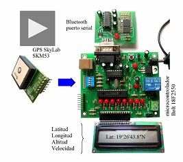
Project: global positioning system with GPS module SkyLab SKM53 and Bolt 18F2550 microcontroller.Author: Moises Melendez Reyes
Background: With the advent of smartphones, it is now feasible for a user to have a complete global positioning system GPS on his/her mobile. This allows to locate his/her position in the terrestrial sphere defined by three geographic coordinates: latitude, longitude and altitude. On the other hand, the miniaturization of the GPS receiver circuits in mobile phones, has in turn made possible the emergence of commercial modules specially designed for interfacing with microcontrollers, using an standard TTL serial interface, such as the SkyLab SKM53 GPS module.
FIGURE 1
Description: Based on Figure 1, the implementation of a GPS tracking system, based on the GPS module SkyLab SKM53 and the Bolt 18F2550 is described in this project. The output data, such as latitude, longitude, altitude and speed, is displayed every 10 seconds, simultaneously on the LCD display and via the standard RS232 serial port of the Bolt card. Alternatively, an HC-06 Bluetooth module may be used to monitor the serial data port on a mobile phone. Connecting the GPS module and the Bolt 18F2550 card is done using its auxiliary port, through a serial interface managed by software in RC0 and RC1 bits of 18F2550, and with TTL compatible levels, as shown in the figure below.
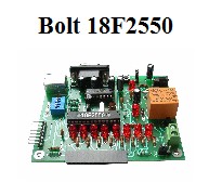
FIGURE 2
For interface with the auxiliary port of Bolt system, the SKM53 GPS module should be powered with 3.9 volts, which requires an AMS1117-3.3 regulator type and a 1N4148 diode connected between the 5 volt pin of the auxiliary port and the GPS module. Electronic diagram here: Bolt-Pic18F2550_Skylab-SKM53_adapter_SCH.pdf Diagram of auxiliary port in Bolt 18F2550 system. Figure 3 shows all devices connected for testing, including a small breadboard to wire the 3.9 volt regulator. For communication between the GPS system SKM53 and the Bolt card, the TX and RX serial port signals are handled by software (through the so-called 'bit bang'), using the transmission and reception bits RC0 and RC1 in the auxiliary port. For proper system operation, the dip switches SW3 and SW4 must be positioned to OFF. The exchange of information between the GPS module and the Bolt card, is performed using the NMEA -0183 protocol, whose specification can be found in the link below.
Firmware: The fimware program in the Bolt card, performs constantly two basic tasks: every 10 seconds receives GPS information, which provides the latitude, longitude, altitude and current speed, and display these variables in both, the LCD display and via the RS232 serial port card. The RS232 serial port can be connected either directly to a computer or laptop PC using a USB-Serial Cable, or use an HC-06 Bluetooth module with serial port to receive the information in a mobile phone .
To show data on the LCD display: To display information on the LCD of the Bolt card ( see photo Figure 3), the user can select with SW1 and SW2 dip switches, the variable to observe as follows. Keep SW3 and SW4 in the OFF state.
FIGURE 3
FIGURE 4: complete GPS SkyLab Bolt 18F2550 kit.
To display data on a PC or laptop computer or a mobile phone: To display the information on your PC or Lap, connect your computer through a USB-Serial cable to the DB9 serial port on the Bolt card. You can use any terminal emulator software (setting: 9600, n, 8,1 ) to receive the data on your computer. However, to observe properly the degree symbol ° we recommend to use the emulator called 'Termite v.3.1' from CompuPhase. The information that the user will see on his/her computer is similar to the following example:
If you want to see the information in a mobile phone or on your Laptop (if equipped with USB - Bluetooth interface), connect a Bluetooth HC-06 module with serial port as shown in Figure 4. On your mobile, you must first load the BlueTerm application from Google Play. Do not forget to link the phone with the Bluetooth HC-06 module before you open the BlueTerm application. On the screen of your mobile, the information coming from the GPS module (through the Bluetooth port of the Bolt card) will be observed, and updated every 10 seconds. In the figure below, an adapter is used for the interface between the SkyLab module and the auxiliar port of Bolt 18F2550 system
FIGURE 4
Important note: to generate geolocation information, the GPS receiver module must maintain communication with at least 3 GPS satellites. The walls and ceilings may prevent the signal from said satellites to reach the GPS receiver, so it is recommended to use it in open spaces. If the GPS receiver does not have enough information from the satellites, on the LCD or PC you will see the message : 'Lat: unavailable'
|