|
project: measuring RMS current with ACS712 Hall effect sensor
and Bolt 18F2550 system.
Author: Moisés Meléndez Reyes
Overview :
Allegro MicroSystems' ACS712 integrated circuit,
allows measurement of current -direct or alternating- flowing in
a conductor.
The desired measured current generates a magnetic field which
the sensor converts to a proportional output voltage,
using the Hall effect.
This voltage in turn is read by a microcontroller system through an A/D
converter to calculate its peak value and the corresponding RMS
value of the load current.
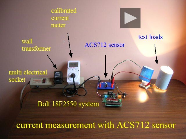
For this project, the test equipment shown in the photo above
was used.
A program in ANSI C for Bolt 18F2550
system, which reads the analog voltage signal generated by
the sensor and displays the ACS712 Irms value in its LCD was
developed.
In tests, a maximum error of 2% in the measurement is obtained by comparing
the values read through the ACS712 and the calibrated current
meter.
As test loads, three 60 watts incandescent bulbs connected in parallel were
used. The project tests took place in Mexico, where the
delivered residential power is 117 VAC, 60 Hz.
There are 3 versions for the ACS712 sensor, for ranges of 5, 20
and 30 amperes.
In the current project the sensor range is 5 amperes, with a sensitivity of
0.185 volts/ampere.
The photos displayed immediately give details of each of the
project components:
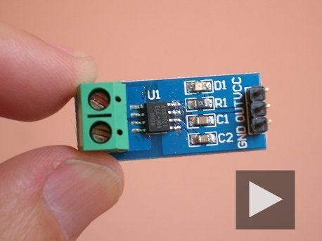
1. ASC712 current sensor:
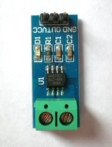
In the
picture, the ACS712
module is shown
and allows connection
to the measuring system in a
simple and safe way: on one side,
the module has connector
screws which
connect to the
power cable terminals.
At the
other end of the module, there is a
3-pin connector, which must be
coupled to the system
microcontroller 18F2550.
Importantly, there is complete
electrical isolation between the
measured current and the
output voltage of the sensor. |
2. Osciloscope readings:
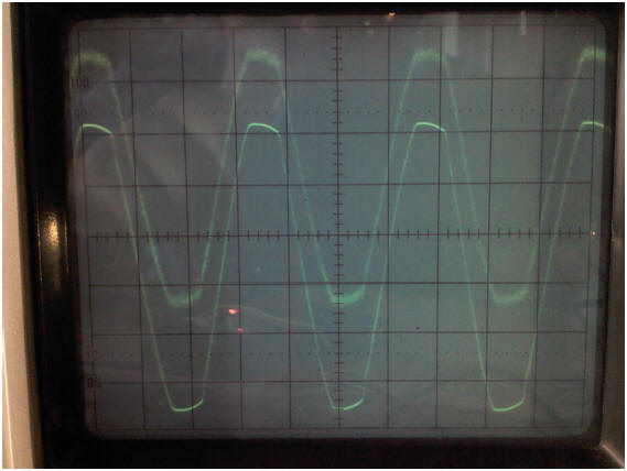
By
observing in the two channels
of an oscilloscope both the
voltage from
117 Vrms mains
and the output signal
from the ACS712 sensor, the
picture shown above is
obtained.
In the picture, the upper signal
is the voltage output
of the sensor ACS712,
(pin 'OUT')
corresponding to a a load current
of about 1 ampere (2
bulbs of 60
watts each). The
signal shown below
is the supply voltage of 117
Vrms.
The sensor signal comprises
a DC component
with a value
of Vcc/2,
in this case approximately
2.5 volts,
plus an AC component
which is directly proportional to
the current to be measured
(the datasheet
of ACS712 shows a
sensitivity is 0.185
volts/ampere, for the
sensor with
a range of 5
amps, which is
being used in this project) |
3. Preparing adecuate connections for ACS712:
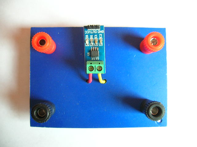
To make
the connection safely
between the sensor
ACS712, the microcontroller
so as to
the 127 VAC load, a
special mount for the
circuit is made.
The
current to be measured flows
through the red terminals,
and through the ACS712 sensor,
while the return cable
is connected to the black
terminals.
|
4. Preparing adecuate connections for ACS712 (2):
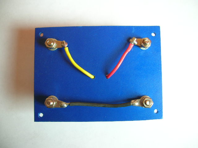
Back view of ACS712 mounting plate.
|
|
5. Connection of ACS712 and Bolt 18F2550 system:
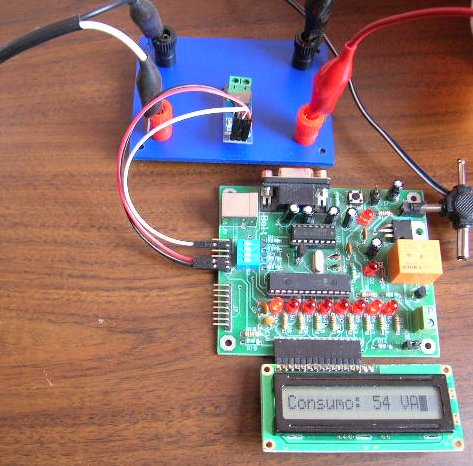
Bolt
18F2550 microcontroller
system, fed from a wall
transformer is connected to the
ACS712 sensor module using
the electronic diagram shown
on the right. The analog
signal generated by the sensor
is input to pin
RA5 of
18F2550.
|
6. Electronic diagram of ACS712 and
microcontroller:
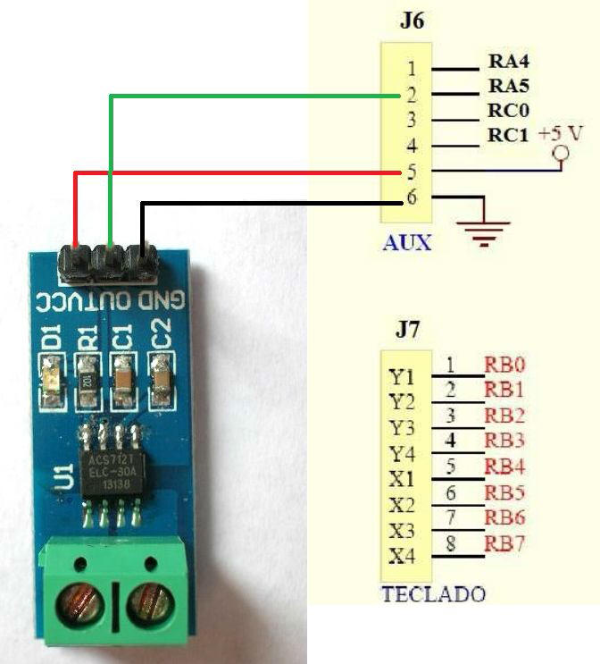
Electronic
diagram of the connections
between Bolt 18F2550
microcontroller system, and
the ACS712 sensor.
The RA5
pin signal on the
auxiliary port is in turn fed to
an A/D converter in the
18F2550.
|
|
7. Test loads using 60 watts incandescent bulbs:
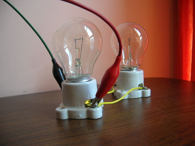
As tests load for this project, two incandescent bulbs of 60
watts each were used, for a total load power of about 120 watts.
|
8. Bolt 18F2550 measuring Irms current:
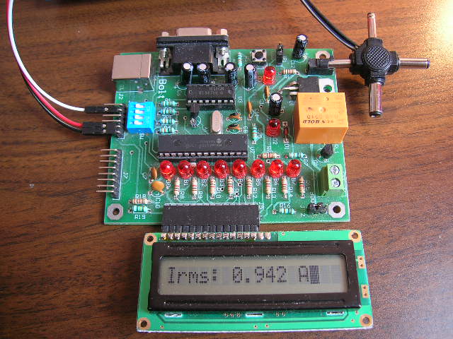
Using the
Bolt 18F2550 system
with a program
developed in
ANSI C,
with the C18 compiler,
the 18F2550
reads the signal from the
sensor through its
A/D converter and calculates
its peak value.
Subsequently, applying arithmetical formulas,
the Irms
value of the current is calculated
as well as consumption in VA.
In this
reading, for a load of 120
watts, a
value of 0.942 amperes of
Irms was obtained. |
|
9. Calibrated current meter:
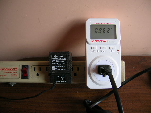
During
testing, a calibrated current
meter was used to perform
comparison with
the readings
obtained by the microcontroller
system. Here, a
reading for a load of
120 watts (2 bulbs of
60 watts), with a value of
0.962 amperes
is shown.
The
comparison of the two readings
gives an error of about
2% for the measurement obtained
with the microcontroller system,
using the following formula: E =
(0.020/0.942) * 100 = 2.12%
|
Firmware for Bolt 18F2550:
|
For the the firmware development, MPLAB-IDE v.8.89
and C18 compiler v.3.42 were used. The folder containing all files
and libraries is given below (for the moment, comments in this files
are in spanish):
Program-Bolt-C18-sensor-ACS712.zip |
Watch video!
|
|