Demonstrative
equipment of a digital automatic level control
of water, with the RG-1045S sensor
and Bolt 18F2550 system.
Project development: Moisés Meléndez Reyes
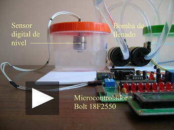
Demo Video in HD:
General description:
In this project, for teaching purposes,
a simple model of an on-off
automatic control filling a water container was
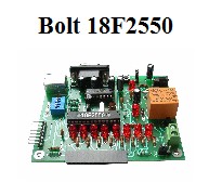
built, using the Bolt 18F2550 system and
the
digital level sensor RG-1045S.
The system can emulate the process repeatedly, and for this purpose includes a
storage container (see Figure 1), which
can be filled again and again through a mini water pump.
It is a control system with1 input and 1
output, ie, the microcontroller Bolt receives a
digital signal in input RC1 and,
through its relay, activate the mini water pump.
In figure 4 the simplified block diagram is shown.
The basic operation of the automatic control is as follows:
if a low water level is detected in the
container (in which case the level sensor will
close its switch), the microcontroller activates the filling
pump.
The water level will rise until the level
sensor switch opens, event that will be
detected by the microcontroller, and the
pump shuts off.
The level sensor has a hysteresis range, such that the water level starts
to decline until the switch is closed again and the mini pump
activates, repeating the filling cycle.
In the
LCD,
Bolt displays the
status of automatic control process, as shown in Figure 2.
If you want to repeat
the experiment with completely empty container control, then the
user has a two-button
manual
control (see Figure 1),
to empty or
fill the container.
For power supply of devices,
two AC/DC adapters are used, which can be
seen in the photo of Figure 1. The first supplies the
two mini water pumps 3 VDC at 1 ampere and
the second feeds the
Bolt
system with a voltage of 7.5 VDC @ 300 ma.
Figure 1:
Devices used in the project.
The green
cap
container
emulates what would be the cistern
and the red cap container,
the water tank that will be
filled. By means of
two buttons,
the pumps can be
activated manually
to
repeat the experiment.
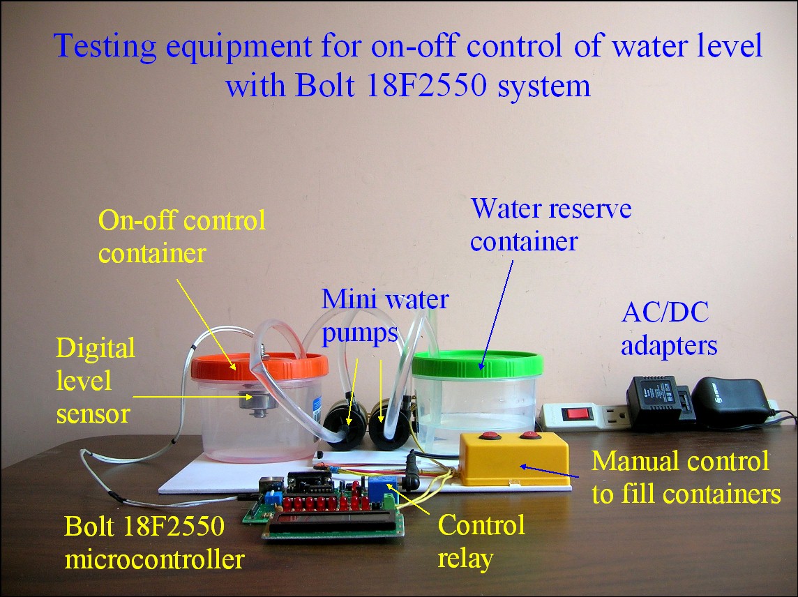
Figure 2:
Top view of the devices. The Bolt
18F2550 microcontroller system uses its
LCD display to show the
status of the process. The microcontroller
receives digital sensor signal
on pin RC1
of
the auxiliary port,
while the relay terminals
(green) are connected to the mini
pump to activate the filling of the container.
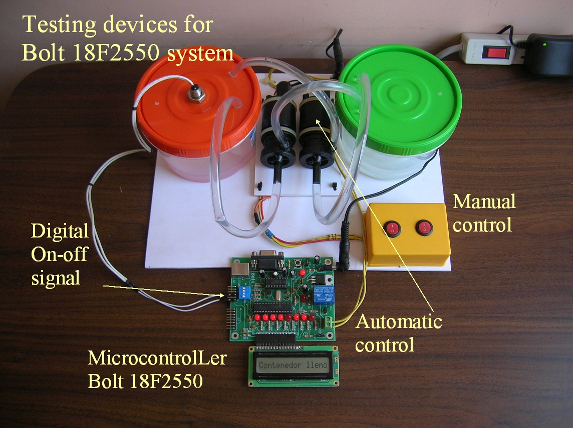
Figure 3: View
of stainless steel level sensor.
It consists of a cylindrical piece with
its hollow interior, so that
when the
water
is
reaching
the maximum level, by flotation, this piece
rises and opens the switch
contacts.
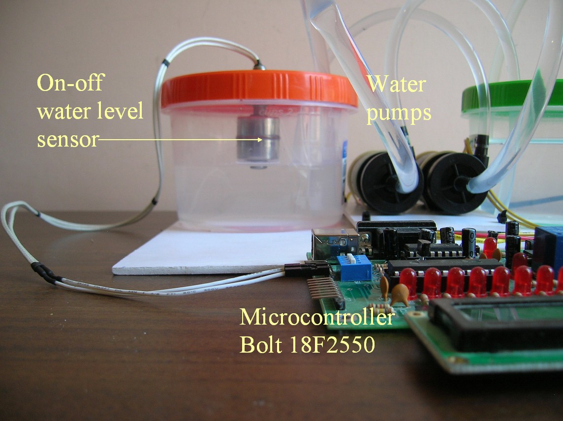
Figure 4: The
sensor can be seen as a normally closed
switch, which opens when the water
level is reached. This signal is fed to the
input RC1
of
Bolt
auxiliary port. The mini
water pump is energized with 3 VDC,
by the microcontroller relay,
as shown in Fig.
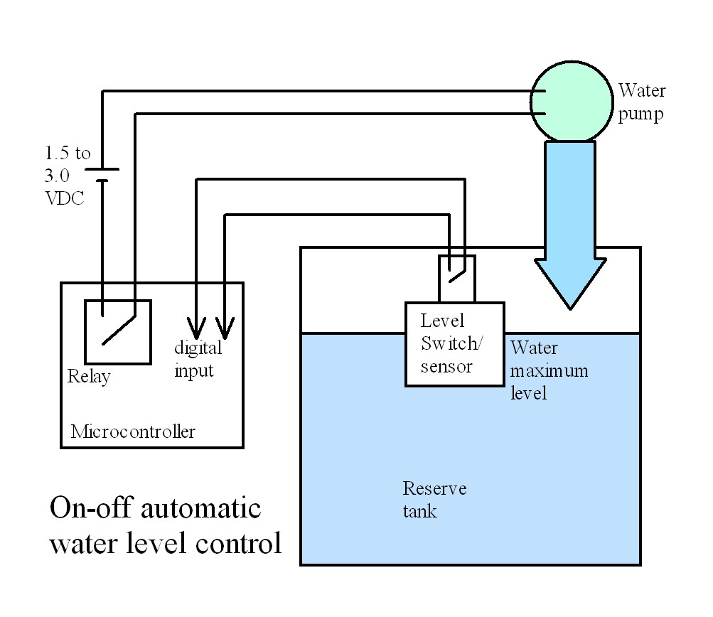
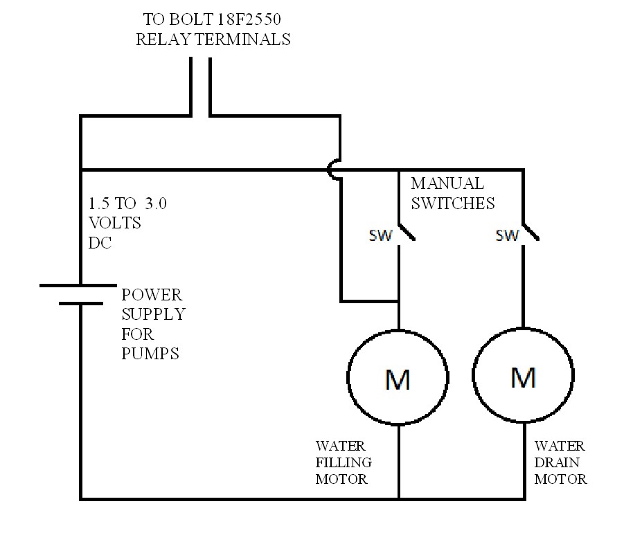
Figure 5: The
electrical connections to
activate
the two
mini water pumps are shown here. Filling
any of the containers can be
done manually by means of two switches
(SW). In automatic mode, the relay
of the
microcontroller
activates the filling pump.
Stainless steel RG-1045S water level switch
Bolt-Firmware-On-Off-Control-Water-Level.zip
|