Tutorial: how a relay works, and its
control from a microcontroller.
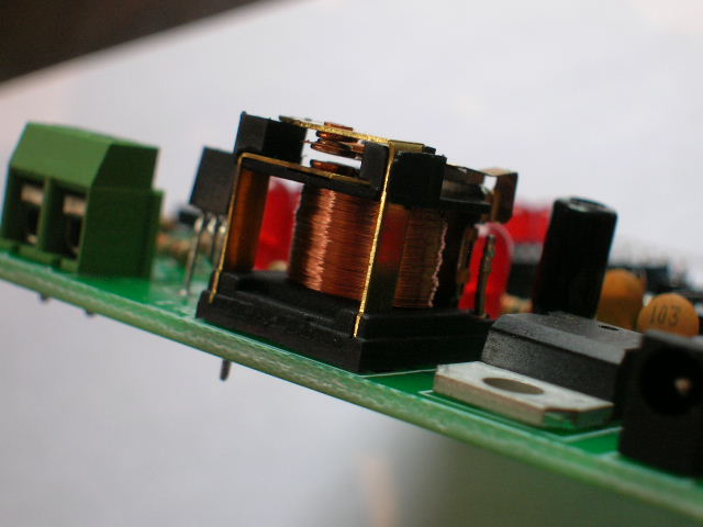
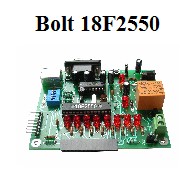
PHOTO: ELECTROMAGNETIC RELAY CONTROLLED BY BOLT 18F2550
SYSTEM
When
designing
an ON-OFF control
project with
a microcontroller, a relay
is commonly used to
activate devices such as
lamps, motors, valves, pumps, contactors,
etc.
The relay most frequently used
is the electromagnetic type, as shown
in the photo above: this
relay works with direct current and
is called a single pole, double throw (SPDT).
This will be explained below with more detail.
For applications not
requiring high frequency switching,
an electromagnetic relay
is the one,
because it has maintained its
low cost, and allows easy
handling of inductive loads (as
would be motors). Moreover, the
acustic feedback generated
upon activation helps technicians locate faulty devices.
When the application requires
switching operation at high
frequencies, as in a PWM
control (for example the
control of motor speed), then solid-state
relays should be used.
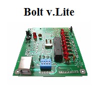
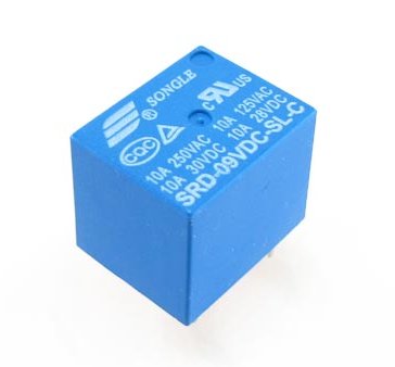
Microcontroller systems such
as Bolt 18F2550,
usually work with
the relay SPDT,
model SRD- 09VDC SONGLE
shown here:
|
ELECTROMAGNETIC RELAY
|
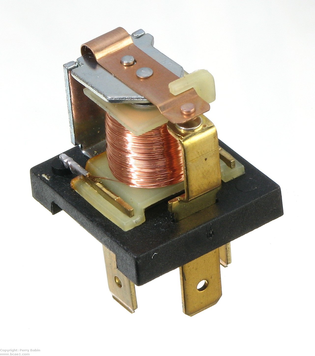
ELECTROMAGNETIC RELAY OPERATION
The
photo on the left shows a relay similar to SRD- 09VDC SONGLE without
its plastic case. It consists of 2 parts: the solenoid (coil) and
the armature. The coil is a copper wire winding on an iron core.
When energized by a direct current, it generates a magnetic field
which attracts the armature to its "Closed" position.
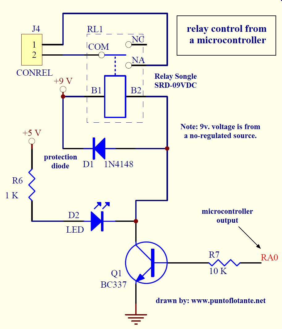
A microcontroller can activate the relay through any of its output
pins, with a circuit as shown in the diagram below.
The relay coil is energized by means of a transistor which acts as a
current amplifier and has its base connected to the output of the
microcontroller, in this case, RA0.
Typically added to the relay control circuit, there is a witness led
(D2) to visually verify the state of the relay, and a protection
diode (called free-wheeling), which absorbs the peak current
generated in the coil of the relay when energized or de-energized.
Without this diode, the transistor would be exposed to surge and
eventually fail. |
|
ELECTRONIC DIAGRAMS FOR DIFFERENT
TYPES OF RELAYS.
|
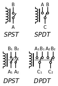
The
relay shown in the
electronic diagram above, is
a SPDT (single
pole, double throw)
type. Some of the distint types of relay
contacts are shown in the image at left.
For a SPDT relay,
when the
device is off,
there is a normally
closed (BC), and a normally open
(AC) contact. When the
relay is activated, the contacts change
their position, closing
and opening contacts AC,
BC respectively (see
left image).
The
relay coil is typically
activated by
an unregulated voltage to
avoid electromagnetic noise
induced on
the regulated supply of
the microcontroller.
To
specify a relay, you must provide
the coil voltage,
the capacity of the
contacts, and the
number of poles and
throws.
For
SONGLE relay
SRD-09VDC, the specifications are:
Its coil voltage:
9v. CD
Capacity of contacts:
10 amp @
127 VAC.
Type: SPDT,
single pole, double throw. |
|