|
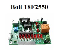
tutorial: the watch dog timer special function for Bolt
18F2550 system.
|
|
|
What is the
purpose of the
special function called
Watch
Dog Timer
WDT?
Imagine you're
working
on your personal computer
typing text
in
a word processor.
Suddenly, without
warning,
the
computer freezes
and does not respond
to the keyboard,
or any of
the
emergency
command,
including
the known
Cnt-Alt-Del.
You come to
the
conclusion that it is
necessary to power
the computer
off and on again
to restore
normal operation.
This event,
relatively common in
personal computers,
is also prevalent in
microcontroller-based
systems
(embedded
systems).
The reason may
be a
software malfunction,
(especially if
it's very complex),
electrical spikes
caused by
lightning strikes
or else
instability in
power
supply voltage. |
|

|
In the example described
above, there is a
human being able to
realize that
the system is
out
of
operation
and therefore
turns the computer
power supply off and on,
that is, performs a
general system
reset.
For
microcontroller systems,
one
of the core design
philosophies
is to guarantee its
continuous operation in field applications,
so that the system will never
remain in an uncontrolled frozen state, since
there will be no
humans present
to press the reset
button of the
microcontroller.
This is achieved
by a
special surveillance
circuit already built into
current
microcontrollers
and
called
Watch
Dog Timer
(WDT).
The
WDT
monitors the
proper functioning of the
firmware
and, if
for any reason
it
goes out of
operation,
performs automatically
a general system reset. |
How to activate
the Watch
Dog Timer
WDT in the
18F2550
Bolt system:
The WDT of 18F2550
microcontroller is a
timer which operates with
an independent clock circuit
with a fixed
frequency of 250
Hz (a period of
4 ms.). There is also
postcaler register
which allows you to program
the WDT
timeout periods
from 4 ms
to 131 seconds.
The microcontroller
has a particular
configuration register
dedicated to the WDT.
It is the CONFIG2H.
This register is
already preprogrammed
with value = 0x1E
in
the
bootloader firmware
18F2550 Bolt
system,
ie, the WDT
is disabled and the
postcaler register
is set to its maximum
value of 32768,
equivalent to a timeout
of 131 seconds.
In the application program, the user may
activate the WDT function by setting the
SWDTEN bit=1.
To view the details
of each bit of the
register referred to, see the following
document:
WDT-CONFIGURATION-FOR-BOLT-18F2550.pdf
If the user
application program
enables the SWDTEN
bit, the
WDT timer
will generate an
automatic reset to the microcontroller
each time it reaches the maximum count
(timeout), that
is, every 131 seconds.
The
C18 ClrWdt ( ) function
resets to zero
the WDT count,
so that, in
the application program,
this function must
run cyclically
and in a
period shorter than 131
seconds.
If the application
program goes out of
operation for any
reason, the
WDT will stop receiving
the signal from the
ClrWdt ( ) function, and therefore will
generate an automatic reset
to the microcontroller
thus ensuring
continuous operation.
Watch Dog Timer test
program for the
18F2550 Bolt
system (131 seconds timeout):
C18-BOLT-WDT.zip
|
If the
user requires to run the
Bolt 18F2550
system
with a WDT and
a timeout
lower than 131 seconds,
a new
firmware bootloader file,
with a modified
CONFIG2H
register must be stored in the 18F2550 chip.
In this case, the user must
utilize an ICSP programmer. The following
file will
generate (if enabled) a WDT
with a timeout
of about 15
seconds:
Boot20MHz-Watch-0X18.hex
To test
this new file you
may use the same
procedure indicated above.
|