|
|
|
|
|


|
|
|
|
|
|
|
|
|
|
|
|
|
|
|
|
|
|
|
|
|
|
|
|
|
|
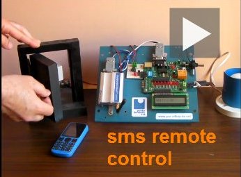
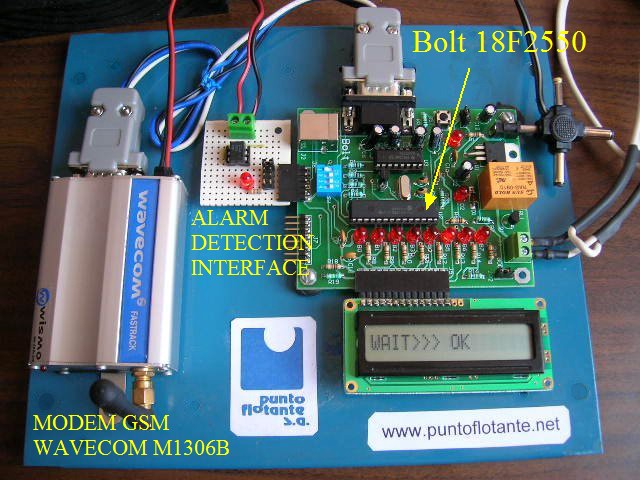
project: Bolt 18F2550 system with a GSM Wavecom M1306B modem, is remotely controlled via SMS messages
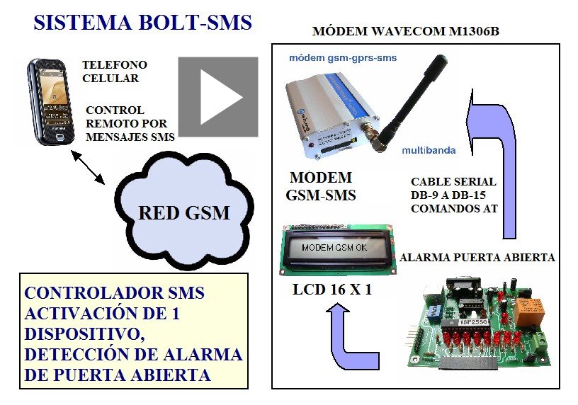
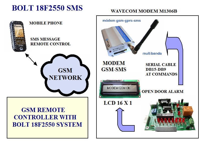
GENERAL DESCRIPTION: In this new project, the Bolt 18f2550 system connected to a GSM Modem Wavecom M1306B, may be remotely controlled via a mobile phone. User may send commands as SMS messages to the Bolt-GSM Modem system, to activate or deactivate a relay, and is also capable of detecting automatically a door open/closed alarm or remotely reading the temperature of sensor DS18B20. This system has the ability to receive up to 4 remote commands through SMS text messages: one to activate or deactivate the system relay. This relay can operate devices such as home electronics appliances, motors, valves, lamps, electric gates, irrigation systems, etc. An additional command, allows a user to remotely receive in its mobile the status of the system, ie the status of the relay (active or inactive) and the door (open or closed). Finally, user can interrogate the system with a command to receive in the mobile phone the temperature reading of sensor DS18B20 (which is integrated into the system). Furthermore, the system employs an alarm detection interface card (see photo) for instantaneously detecting an alarm when opening or closing a door. The Bolt-GSM system sends an automatic SMS message to alert the registered user of the event. System information step by step, is shown in LCD in real time, providing status throughout all the functions being carried out by Bolt-GSM modem system. The LCD display is used to display system status, so that a supervisor may recognize the modem initialization phase, the reading of the intensity of the signal, the modem connection to the GSM network and the received SMS messages, as well as the identification of the mobile phone that sent the SMS. Also shown in the LCD, is the process of sending the SMS message confirmation to a mobile when the command is succesfully executed. The connection between the Bolt system and the GSM modem was made with a DB9 to DB15 serial cable, as shown. Only signals TX, RX and ground were used. The control of GSM modem was made through AT commands sent over the serial RS232 interface. Source files of the program developed in ANSI C for Bolt 18F2550 system are provided with a detailed explanation of the functions used, so that the interested user can assemble its own application. BLOCK DIAGRAM OF BOLT-SMS SYSTEM:
BOLT-GSM SYSTEM
FIRMWARE:
COMMANDS:
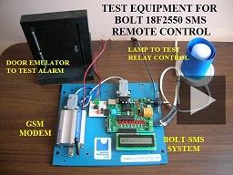
The password consists of 4 characters that can be uppercase or lowercase letters and numbers. The test program has the password "WAV ", ie W, A, V, <space>. If the user wants to change the password, it must do so in the source program. Note: SMS messages are sent from any mobile to the phone number of the GSM modem with a SIM card installed. TESTS: Using the equipment shown in the photo, tests were made for each of the commands of the table, sending SMS messages from a mobile to the Bolt-GSM system. In the alarm door emulator, magnetic switches were installed. When the door is opened or closed, a SMS message is sent to the mobile phone alerting this event. To carry out the tests is important to keep the microswitch SW1 in "OFF" position, otherwise the door open alarm will not work properly. However, this microswitch may also serve to simulate the door opening. TEST EQUIPMENT:
|