HOME

PROJECTS

TUTORIALS

C FUNCTIONS

PROGRAMS

PRODUCTS

VIDEOS

COMPANY

SPANISH


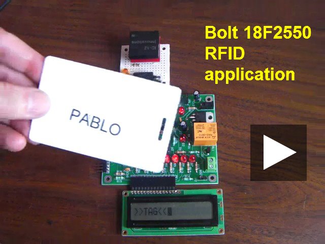
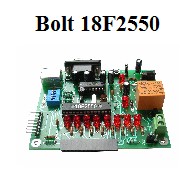
Using Bolt 18F2550 system for RFID applications


Video: Bolt 18F2550 system with RFID interface


GENERAL DESCRIPTION:

An access control pilot project was developed  based on the ID-12 detector circuit, with integrated antenna, and EM-4002 plastic cards. Thanks to the 18F2550 large FLASH memory capacity, it is posible to implement a small data base for the access control.

The ID-12 was adapted to a circuit with a DB9 serial connector to interface with the Bolt-18F2550 system, as shown in the photo.

You may see a 10 second video of project by clicking in the left photo.


tag.jpg (27233 bytes)


When the plastic card or tag as the one shown left approaches a distance equal to or less than 10 cms to the RFID scanner, it sends the identification of the tag through its serial port. The identification number is a string of 16 bytes, 12 of which are hexadecimal data (48 bits) encoded in ASCII characters.

Bolt 18F2550 system receives this data and displays the information on a LCD 16 x 1. Several test programs for the C18 compiler were developed. A complete block diagram for the project is shown below.


FORMAT OF STRING: A TOTAL OF 16 BYTES

STX (02H) DATA (10 ASCII) CHECK SUM (2 ASCII) CR LF ETX (03H)


Photo at left shows the RFID system assembled and connected to the PC computer via a USB cable. It is also possible to feed the system through the power jack in Bolt card and use an external wall transformer.

Power supply of 5 volts for the RFID module is fed through pin 7 of DB9 in Bolt 18F2550 system.

Each plastic card EM4002, contains a unique identification, factory prerecorded in a microchip. This microchip sends the identification automatically via radio link (frequency channel, 125 kHz) when the card is about 10 cm from the detector.


With a buzzer and an LED, visual and audible feedback are provided to the user whenever the scanner circuit ID-12 recognizes and validates the digital information from the card EM4002.

The scanner ID-12 receives the data, decodes and feeds a string of ASCII characters to the serial port of Bolt 18F2550 microcontroller. Configuration of serial port is 9600,n,8,1.

The 10 data and the 2 check sum characters that constitute the TAG identification (48 bits), are displayed in the LCD 16 x 1 as shown.

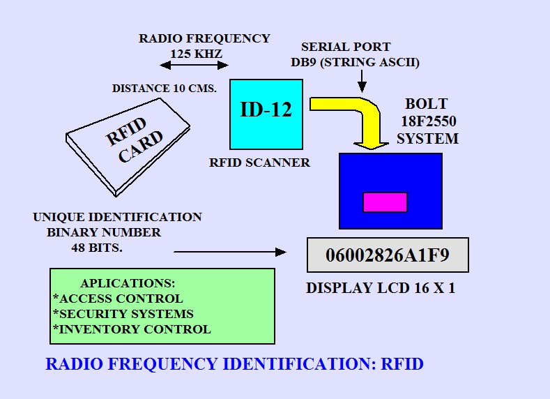
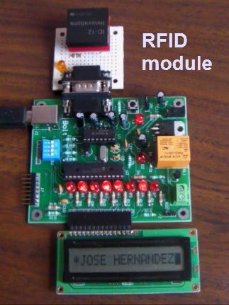
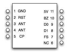
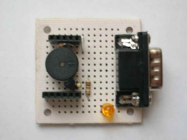
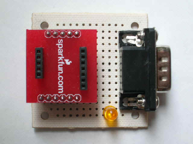
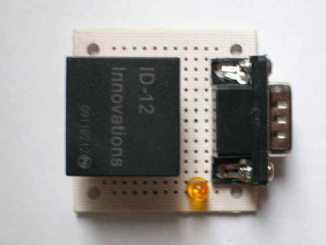
HARDWARE DETAILS OF RFID MODULE FOR BOLT 18F2550 SYSTEM:


id12221.jpg (20349 bytes)

ID-12 SCANNER


ID-12 PINES.jpg (44545 bytes)

SIGNALS IN ID-12 CIRCUIT


ID12 005.jpg (70304 bytes)

SPECIAL SOCKET FOR ID-12


ID12 006.jpg (68327 bytes)

BUZZER IN PROTOTYPE


ID12 008.jpg (75411 bytes)

SOCKET FOR ID-12


ID12 009.jpg (67438 bytes)

PROTOTYPE READY

Electronic diagram: DIAGRAM RFID.pdf

C18 APPLICATION PROGRAM HANDLING BIDIMENSIONAL ARRAYS

The application program contains the basic functions of the access control: identification of tag, comparison with a bidimensional array data and then display the name of the person on the LCD display 16 x 1. As an extension of the project, it is possible to add communication between the Bolt 18F2550 system and a PC to handle large data bases.

The program was developed using the C18 compiler v.3.40 and MPLAB IDE v.8.63. Using the capabilities of the C18 compiler, we used a two-dimensional array to store the list of names and ID codes.

A basic test program was done first: C18-BOLT-RFID.c

The complete application program is: C18-BOLT-RFID-3.c

Accompanying libraries can be found here.

In the application program, only 8 records were stored (one record per person), but could be up to 100 without any problems in the use of memory, which would consume only 2K of the 32K available. Note how the last 4 digits of the tag and the name of the person are stored in the same array, so as to facilitate identification.

Also, using the facilities for handling pointers, an array of arrays called "masterarray [ ]", based on pointers, is defined. This makes it possible to access any array element. The definition of the arrays used in the program is the following:

const char TAG[ ]=">>TAG<<";
const char s1[ ]="19AEJOSE HERNANDEZ"; //LAST 4 DIGITS OF TAG AND NAME OF PERSON
const char s2[ ]="F1F9PABLO JIMENEZ ";
const char s3[ ]="1BACPAOLA ESPINOZA";
const char s4[ ]="1AADJAIME BETANZOS";
const char s5[ ]="F28DLUIS ROBLEDO ";
const char s6[ ]="A723ROBERTO LIMON ";
const char s7[ ]="29E6JOHN CASTELAR ";
const char s8[ ]="359ADAISY PEREZ       ";
const char *masterarray[ ]={s1,s2,s3,s4,s5,s6,s7,s8}; //ARRAY OF ARRAYS

A single standard function of C18 is used to read the string of 12 characters sent by the RFID module to Bolt system:

getsUSART(array,12);