|
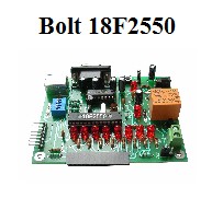
project: infrared
remote control for Bolt 18F2550 system, using an RC-5 Philips
protocol.
This project is based on
Christian Stadler work, published in the link
www.picprojects.net
Modifications to the firmware were made for correct functioning
with the hardware configuration of Bolt 18F2550 system and its
bootloader.
Introduction:
Infrared (IR) remote controls
for TV, audio and video home appliances are cheap
and easy to get in retailer stores. While there are several IR
remote control protocols used by different manufacturers, one
distinguishes as a quasi standard for the industry: the RC-5
protocol, developed by Philips in the late 1980, and presently
still used by many manufacturers.
The IR handset contains a keypad and a
transmitter integrated circuit driving an IR led. The command
data is a Manchester coded bitstream modulating a 36 kHz carrier.
(Often the carrier used maybe 38 kHz or 40 kHz) The IR signal
from the transmitter is detected up to 10 meters meters away by a specialized IR receiver
(TMF5360)
with a photo-diode, where it is amplified, filtered, and demodulated
so that the receiving device can act upon the command sent.
The RC-5 Philips protocol provides a one-way link, with information traveling from
the handset to the receiving unit. Distance from IR handset to the
receiving microcontroller may be as far as 10 to 12 mts.
Description:
Using the Bolt 18F2550
system, an IR receiver circuit interface and firmware
for the 18F2550 microcontroller was
developed to decode the signals sent by a Philips RC-5 protocol
IR
remote control handset. The IR receiver circuit, based on the
TMF5360 or
TSOP1736,
is
inserted to the 14 pin LCD connector of the Bolt board. The signal
enters
the 18F2550 microcontroller through the RB4 bit.
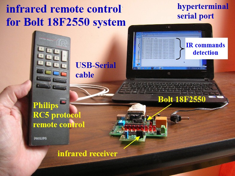
Each time the user sends a remote
command from his IR handset, it is first demodulated by the IR
receiver circuit. Then the firmware of Bolt 18F2550 system
microcontroller decodes
the signal and generates a 9600 bps message to the serial port,
which may be observed using an Hyperterminal software in any PC.
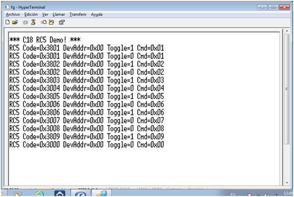
Experiments were made pushing each
of the 0 to 9 buttons of the handset, as shown in the photos
below. For example, if user pushes button 6, will obtain a
message in the serial port which reads:
RC5 Code=0x3006
DevAddr=0x00 Toggle=1 Cmd=0x06
Please note that the last
number of the line indicates the command sent by the IR remote
control, so changes to the firmware may be
easily made to handle a task for each received command, for
example activate or deactivate the relay.
|
Complete
MPLAB-IDE firmware files:
C18-ALL-BOLT-INFRARED-REMOTE-CONTROL.zip
In this folder, you will find 2 applications: one is to send the
decoded information of the infrared remote control
to the serial port at 9600 bps. The second is to
control the relay remotelly with commands '1' and
'2'.
In the first
application, to test the program with the serial
port, load the
.hex file to the Bolt 18F2550 system and connect
devices as shown in photo.
C18-BOLT-INFRARED-REMOTE-CONTROL.hex
Use a USB-Serial cable
from the Bolt board to the PC. You may either feed
the board with an external wall transformer (as in
photo) or directly through the USB port. You must
first open the Hyperterminal program (9600 bps) and
then
reset the Bolt board to start program.
In the second
application, if you wish
to have a remote control over the relay of your Bolt
18F2550 board, you do not need to connect your Bolt
board to the PC computer and instead you may feed it
from an external wall transformer. With command 1 activating the relay
and command 2 deactivating it, the executable file
is:
C18-BOLT-INFRARED-REMOTE-CONTROL-RELAY.hex Important:
not every IR universal remote control handset will
work. It must operate with the RC-5 Philips protocol.
However, RC-5 is an industry standard and many
manufaturers sell IR products that work using this
protocol.
|
CONNECT DEVICES AS
SHOWN:
WATCH MESSAGES IN HYPERTERMINAL AFTER EACH
COMMAND IS SENT:
|
 |
The
firmware decodes the signal and the microcontroller
generates a 9600 bps message to the serial port,
which may be observed using an Hyperterminal
software in any PC.
Experiments were made
pushing each of the 0 to 9 buttons of the handset,
as shown. For example if user pushes button 6, will
obtain a message which reads at the end: Cmd=0x06
Changes to the
firmware may be easily made to handle a task for
each received command, for example activate or
deactivate the relay. |
THE ELECTRONIC DIAGRAM OF THE IR
RECEIVER IS AS FOLLOWS:
|
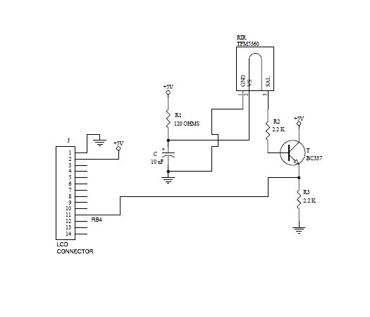 |
The IR
receiver interface uses an
TMF5360 circuit, but it
may be assembled with any other equivalent IC.
The decoded ouput
produced by the
TMF5360 circuit is connected to RB4 in
the 14 pin connector of Bolt board. The
BC337 transistor is an amplifier for the signal,
to drive led B4 in the Bolt board.
The TMF5360 responds to
signals received as far as 10 to 12 meters from the IR
remote control handset.
R1=120 ohm, R2=2.2k,
R3=2.2k |
|
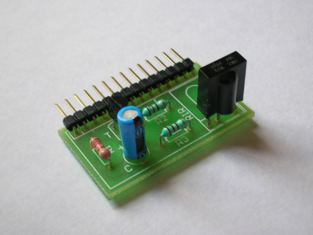 |
The design
of the IR receiver in a small PCB permits to handle the
TMF5360 in a vertical or horizontal position,
depending on the user needs, for optimum
reception of IR signal.
The circuit has 14 pins
and in inserted to the LCD connector of Bolt
18F2550.
Each time the user pushes
a button of the IR remote control, you will see
leds B0 and B4 of Bolt 18F2550 flashing.
Led B4 indicates that the
IR signal is being correctly received from the
IR remote control. Led B0 shows the decoded
signal coming out from the microcontroller. |
|