|
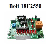
Project: 4 applications for
TM1637 seven segment display circuit connected to Bolt 18F2550
microcontroller
Author: Moises Melendez Reyes
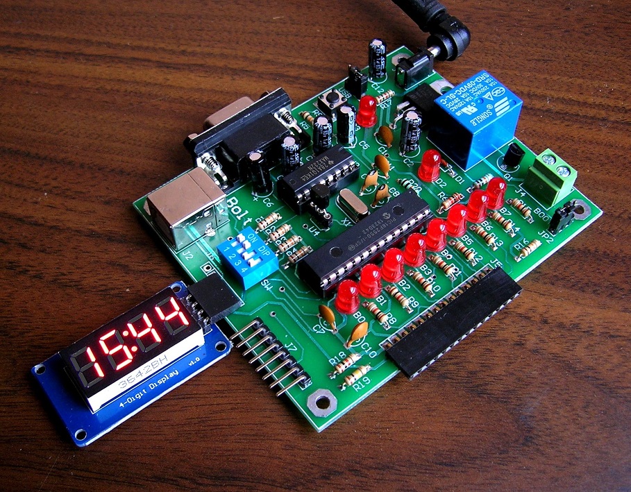
Figure 1: Display TM1637 is
connected to the auxiliar port of Bolt 18F2550 board
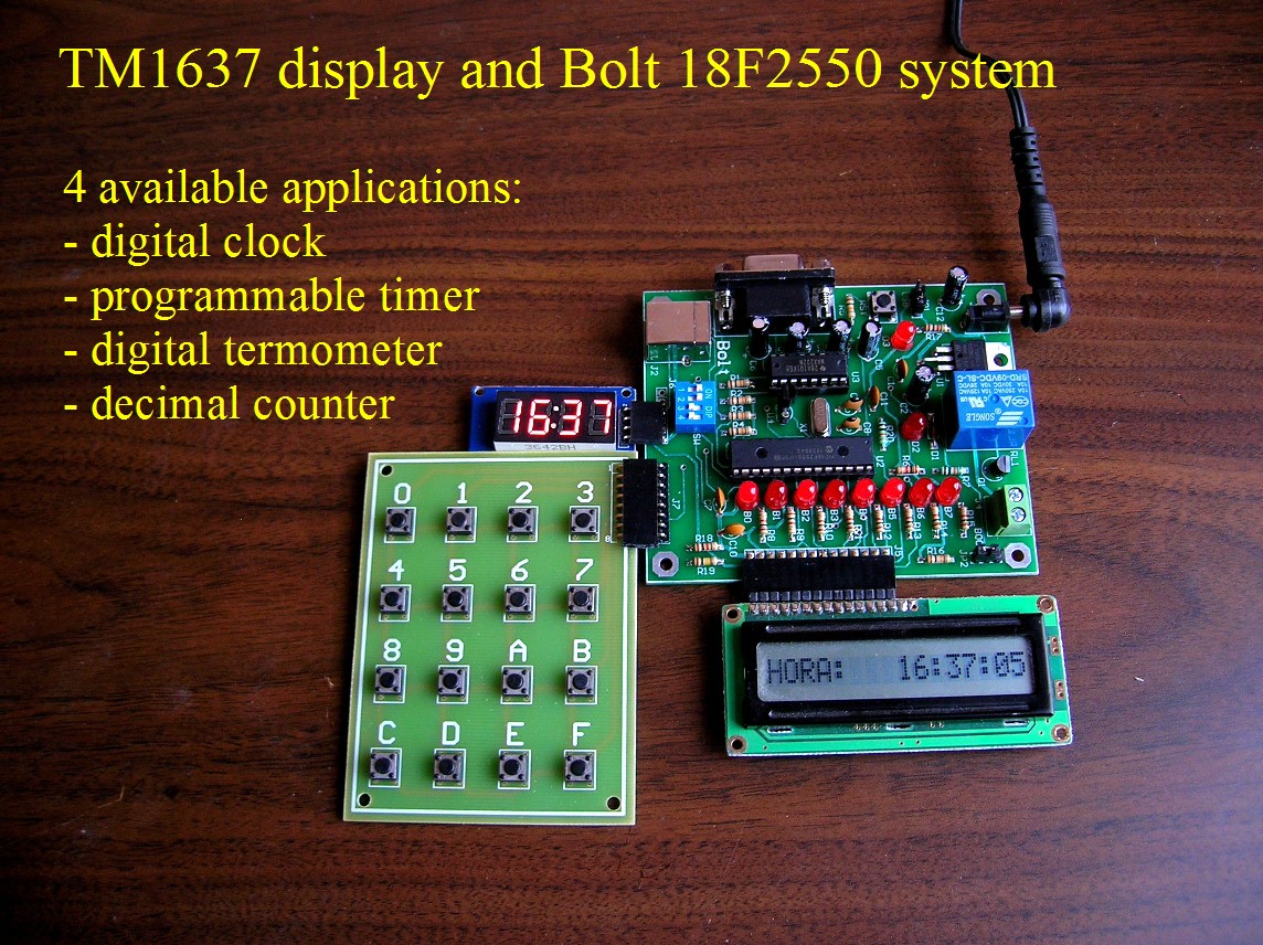
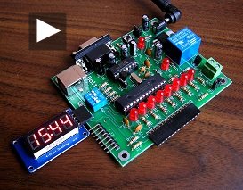
Figure 2: additional devices
assembled to test TM1637 applications
1. Overview:
The TM1637
device, 7-segment
display with 4 digits
is an inexpensive circuit, simple to
incorporate to
microcontrollers. The connection
is performed using the
protocol known as TWI
(two wire
interface) with 4 signals:
Vcc, GND and 2
signal for
the synchronous
serial interface.
In this project
the development of 4
applications for this
display and
18F2550 Bolt
system is described:
* Real time clock.
The user must enter
data using the keypad. The
LCD display
shows data, including
seconds.
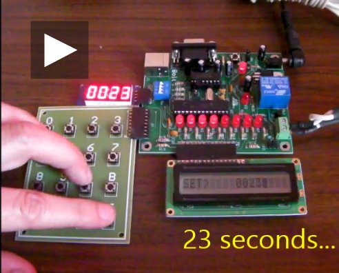
* Programmable timer,
with input
of minutes and
seconds from the keypad.
The relay is
activated when the
count reaches zero.
* Digital thermometer
in Celsius,
with reading from
DS18B20 temperature sensor.
* Basic test program:
decimal
counter.
2.
Assembling the system:
Assemble all devices
as shown in photos of
Figures 2 and 3.
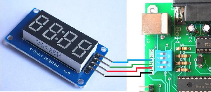
The TM1637
four pin connector is
directly compatible with
the auxiliary port
of Bolt 18F2550
system. The user can
make the
connection directly or
through dupont
type cables.
Optionally, it is
possible to feed the
Bolt card
either through
a USB cable from a PC
computer, or through an AC/DC
external
adapter
as shown in Figure 2.
Figure 3: pins of
TM1637 are compatible with Bolt 18F2550 auxiliary port
3.
Control Program:
The entire project done
for Bolt
18F2550 system with
the environment
MPLAB IDE
and C18
compiler is included in
the following file.
The .hex
executable file is in the
folder named 'release'.
It also contains a manual
system operation.
TM1637_BOLT_3.rar
Once
the executable file is
loaded in the Bolt
card, the following 4 applications
are available
and are selectable
via dip
switches SW1
and SW2
of Bolt
system, depending on the
following table. If the
selection is changed,
the reset button on
the Bolt
card must
be pushed to
activate the new application.
Important notice:
the dip
switches SW3
and SW4
must be in the OFF
position to prevent them
from interfering with
the operation of the
display.
|
SW2 |
SW1 |
FUNCTION |
|
ON |
ON |
Displays
time in 24 hour format. Input time from keypad. |
|
ON |
OFF |
Displays
temperature in degrees centigrades |
|
OFF |
ON |
Basic test
program. Displays decimal counter from 0000 to 9999 |
|
OFF |
OFF |
Timer
application, with a range of 1 hour. Input data from
keypad. Activates relay when count reaches 0 |
|